Brief Update – Model Railroad

Yeah, it’s another one of those.

My terminal strips came in, and I’ve now completely wired the track blocks on both sections. Now I just need the other ATX extensions to arrive so I can wire the connections between the two sections and start running trains again.

A week or two ago I pulled out a scrap piece of plywood (roughly 1’x8′) and laid out the track work for a time-saver layout. At some point I think I’ll get things together to build frame work and put that together as well – I like the game aspect of it. I already have a short list of things I’ll do differently – for one I plan to lay cork under the track. I want to try different wiring techniques like soldering to the bottom of rail joiners – we’ll see how that works out. Once track is laid and wiring is done it will certainly take a back seat to the slightly bigger project (the one I’m working on now).

The current layout doesn’t have a name yet… I haven’t come up with something that I like that I can enjoy. I thought about “Dufflyn,” because it is a location at the end of a branch line, ie “End of Line” -> “[En]Dufflyn” but I still think it’s a little too cheesy.

Model Trains Update

It’s been a while since I posted an update on where my model is at, mostly because it’s been a while since I did anything really observable.

Recently, however, I brought the two sections inside from the garage and did a lot of work on wiring them properly. I’ve also bought some cheap parts to finish the job, and I should be set to finish putting wires underneath some time next week. Then it will be on to building a control panel to tie it all together.

The left section is fully wired for track circuits underneath, and this is where the main connection with the control panel will be. The two sections will be electrically connected using 20-pin ATX cables – one side will have a male connector and the other will have a female, and a small extension cable will connect the two together. Connecting to the control panel is another story – a 24-pin ATX connection is being used to begin with, but it won’t be enough on it’s own. This is still to be decided..

The right section is primarily wired for track circuits – I’m awaiting some terminal blocks to arrive so I can wire them all the way to the end. Also, once terminal blocks arrive I can really get moving on wiring turnouts – at present I have one pair of turnouts (a crossover on the left section) wired to a terminal block, but then I ran out of terminals, and so it stalled.

I’m shortly expecting a set of couplers to arrive, ordered for my 4 IHC passenger cars to bring them ‘up to standard’ (IE, have knuckle couplers..). They should be here tomorrow! I also have a bunch of LEDs and resistors for an upcoming project to change the way my locomotive lights work. Hopefully it will also be easily transferred to DCC when the time comes.

I was surprised to find a train set at Gift and Thrift in Harrisonburg a week or so ago, and I bought some parts of it. A Great Northern box car which will end up as scenery, a Chessie System caboose which will also be scenery, and three small Bachmann hoppers (two N&Ws and a Southern). These are on my list to replace with knuckle couplers too, however I need knuckles with a mounting hole smaller than that of a #5 Kadee, but larger than that of a typical Tyco model. I suspect further research is required!

So, hopefully by the end of this coming week I may be able to run trains again! We’ll see.. Here are some photos. I apologize for the lack of quality, I used my cell phone camera!

This is the underside view of the wiring for the first pair of turnouts to a terminal block. This will eventually be wired to the main terminal block (to the left in photo).

And this is the top view.

This is the left hand module, to the left is the main terminal block which has all 8 blocks of track circuits wired for both sections plus common. To the top is the connection to the right hand section, which is yet to receive the remaining turnout wiring.

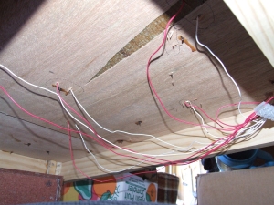
This is an overall underside view of both sections.

And an overall top-side view of both sections.

This is the underside view of the wiring for the first pair of turnouts to a terminal block. This will eventually be wired to the main terminal block (to the left in photo).

Diary, Model Railroad, 7, etc..

This is really stretching out! Anyway, since the last post I’ve done little but prepared much. Or at least, that’s what I’m telling myself.

What I’ve achieved: Completed painting both sections.

Yes, that’s all.

That said, I have ordered more ballast (since I have one pack of light and two packs of dark – not very close to meeting my requirements), I have ordered more terminal blocks (so I can rewire the second section much more cleanly), I have ordered a 20->24 pin ATX adapter and a 24->20 pin ATX adapter – this should give me both male and female sockets for 20 and 24 pin. I’ve also ordered DPDT switches and momentary on switches – enough to build a control panel. I’ve also printed onto paper some cardstock buildings, and I’ll be gluing those to the poster board that I also acquired at some point in the near future.

My coming plans involve forming a road (I’m thinking a paved road and a dirt/gravel road or two) through part of a section. The problem I’m having is deciding where. I thought I had left space in the track layout, but it seems there are some tight spaces where I’m thinking of putting buildings. It would also be cool to have a rail-in-road space somewhere, I’m thinking along the back where I was planning on putting a one-car container terminal, and building a fence around the facility for security etc. Lastly, I realized that I hadn’t made any account for uncoupling magnets, and I don’t like the idea of them being incredibly visible (unless they can be disguised as something else in some way?) Therefore I either need to lift pieces of track just enough to squeeze magnets in underneath (perhaps thin magnets?) or use stronger ones under the baseboard.

These problems and more to be found and hopefully resolved, soon. Here are some photos.

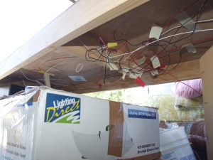
The messy module is seen above a Lighting Direct box (all the way from New Zealand). It is also the one with the least paint (although it is now finished – no photos as yet.) The other module is facing the wrong way, but is otherwise ready for the next step, whatever that may end up being.

Diary of a Model Railroad, part… 6?

I think I’m up to part 6, at least. Anyway, there was a long period of no-development on the layout mostly due to finance. I now have a job (cheers, applause, etc, etc) which means in addition to being able to pay all our bills, we have enough spare money that I can devote a little more to the trains.

A while back I picked up a cheap terminal block on eBay, and will likely need another one soon for the other half. Also, I bought a sampler-sized pot of brown paint yesterday and I utilized both the terminal block and the paint this morning.

So today there were three things achieved, albeit small. Firstly I replaced a section of track that had been bothering me for a while, ever since I laid it and it didn’t really work out. So today it was removed and replaced with a better job. I’m yet to test it, but it looked fine to the eyes.

The second job was rewiring the underside of one module using the terminal block. It now looks a lot tidier, and I just need to run the master feeds back to the end and work out how I’m going to connect the two modules electrically.

The third and final task completed today was painting around the track with the brown paint. The idea behind this is that when I put down grass or whatever other scenery, if it becomes chipped or I miss a spot, it looks more like dirt than just a piece of real-sized hardboard. It probably needs a second coat, but that will have to wait.

That leaves my to-do list rather short: I need to figure out the electrical connections (20/24 pin ATX connectors?), I need to figure out how I’m going to cover or otherwise hide the turnout motors (long ones, sitting along the straight-leg of each one) and I need to actually wire the turnouts, even if they don’t go anywhere. I’m also planning on ballasting track soon, so my t0-buy list is slowly growing again: another pack of lighter colored ballast, another terminal block, some DPDT switches and some momentary switches for the atlas turnout motors.

Diary of a Model Railroad, Part Five

Alright, alright. Yesterday I promised photos. But today I’m too excited to wait until I’ve uploaded them all – it’s done!

I once heard on a video that “a model railway can be finished, but it is never completed.” This is very much true for mine, which is presently nameless. I finished up the wiring this morning and tested it all, and all tracks work electrically, and I was able to fix most of the problems. I have a couple of pieces that I will need to pull out and actually fix (including a very sharp turn that I was aware of when laying, but ignored. Now I get to fix it.)

It is a very operationally intense layout. To get any of the cars from storage to a business requires the loco to run around them, and with one exception requires at least one switchback. I’ll draw up a diagram later and probably post tomorrow (with photos?) to show where things are and how it is intended to work.

Once I fix the couple of minor track faults I’ll be ready to consider scenery. I also need to create a control panel which will also involve tidying up the wirings underneath, then I can look at wiring turnout motors (and hoping they all work electrically). Another pressing issue is the electrical connections between the two sections and the control panel. The right side needs to have 4 blocks plus ground (so 5 pins) and the left needs 6 blocks plus ground (7 pins). Additionally, the left side has 5 turnouts that need to be switched and the right side has 8. Some of those can be combined, but I still need 4 pairs of circuits (9 pins – 4×2+ground) to the left and at least 4, possibly 5 or 6 to the right.

Such questions can wait to be answered tomorrow. I have more practical things to do tonight, like socializing!

Diary of a Model Railroad, Part Four

I had hoped to have some more photos ready for this post, but they’re on my camera and that’s in the car, 20 minutes away. Maybe next time.

Anyway, I have very nearly completed the first half of the layout. The right-hand side has all but two pieces of track laid, and all but one set of track feeders in place. I’ve begun laying the matching track pieces on the left hand side, and this is basically where I’m holding myself up. 4 pieces of track cross the line between the two sides, and of these 2 are done and dusted. The third needs me to lay a curved piece of flex track across the line, and this is where I lose excitement. I want to do this section first, because the fourth and final section to cross the line is the one that actually has a useful purpose on the left hand side, rather than just being sidings to store cars for businesses that the model will ‘serve.’

I divided the whole layout into several sections. I doubt I’ll ever operate it with more than one person, but in theory it could be operated with two engines, and with the split sections that becomes a little easier with basic DC power (since I’m underfunded for DCC right now..). For now I’m tying all of the feeders for the sections to each other and then I’ll link those to a single pair of wires to the controller until I make a real control panel with switches etc. I also need to find some 3-way wire to wire the turnout motors, but again that can wait. My goal is to be able to drive on at least part of it by the end of the week.

In other news, I’m fast running out of solder, so I may need to hunt down some more..

Diary of a Model Railroad, Part Three

Finished! Well, not quite. The bench-work is mostly finished. It needs to be sanded off at the ends especially, and I still need to finalize how they will attach to each other. I’m thinking maybe a clip on each side to hold it horizontally, and maybe a door lock thing to hold them in alignment? Other than that, I’m mostly happy. I have photos too, I’ll tell the story from when I started (again – the successful attempt ;-))

July 7th

It starts out with Crash looking like a lazy dog. He really is.

This is an overview of where I was up to on July 7th. The outer frame of one section was complete, and the cuts had been made for the second section, with pieces screwed in to line the up, it was ready to glue and screw together.
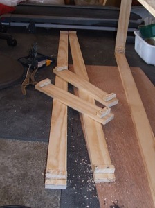
These are the pieces. Give or take (I measured them to be the same length as each other, not to an exact number of inches) they are 2x 5 foot pieces and 2x 1.2 foot pieces. Screwed and glued into each are two 3/4″ x 3/4″ pieces which are used to easily align each piece with it’s join partner. They are then glued at the corners and clamped together for a couple of hours, then screwed. Below, an end has been glued and clamped.

July 8th

I realized that there wasn’t a great deal of structural support, and that for sections that are likely to be pulled out and put away fairly regularly support is probably a good idea. So I measured and cut two support pieces to fit roughly half-way down each section and then drilled three half-inch holes for wiring to go through, and glued and screwed in the same way as the rest of the base. Here, the first is clamped and waiting for glue to dry.

The support supports are gluing on the second frame, when these are dry some more they will be screwed down into the outer frame and the support will be glued to them and then screwed.

I hung out with Crash for a bit while the glue dried!

The frames were finally finished. One is fairly warped, but I don’t plan on exhibiting this layout and it’ll likely be warped with time and transporting anyway, so I’m not overly worried. With the ply nailed down, it doesn’t seem too terrible. I doubt it will cause any major issues (famous last words?)

July 9th

“I claim this foot in the name of Doglandia Forever Woof Woof!”
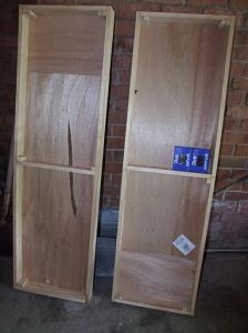
I nailed down the tops this morning. Here are both from the bottom…
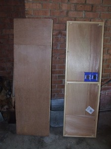
And one from the top. Basically, because they are 5 ft by 1.5 ft each, I used a 4ft square piece of ply and cut two lengths of 4′ x 1.5′ and then two pieces of 1′ x 1.5′ and had a 1′ square left over.

This is the end of one of the sections – both sections have one end like this (I guess the sides weren’t exactly 5′ long!) and one has sides that are a little like this too. They’ll both get sanded back at some point, probably next week now.

I only had 3 incidents while nailing. Two like this, where I nailed at an angle far enough that it poked through the frame. One on each section, and I was able to push them back out so that with some sanding they probably won’t be noticed. I’m considering some 1×4 to go around this all, partly for strength, partly for keeping most track below top surface level (and thus protected a little more). The third incident was near the end of the first section. I’d been using a pair of vice grips to hold the nails to try and keep them vertical, and I elected to do one with just my fingers. Some of you may have seen my earlier tweet that read “OW! Thumb + hammer = pain” – and that’s precisely what happened. Fortunately it is my left thumb that is afflicted, so while it is still pulsing a little (some two hours after I hit it) it’s not causing me too much problem.

Diary of a Model Railroad, Part Two

The last update on this project was two months ago. Far too long, now that I am thinking about it.

However, progress is finally being made. I forgot at the beginning, that my ability to cut straight is entirely defined by what I happen to be using as a guide. When that guide is my eye and a steady hand, it doesn’t work out so well.

I had to use one of my 1×3’s to reinforce some of the breaking slats on the base for our bed, so it was a useful way to recycle the cuts I had made that were mostly useless for this project anyway. Now having borrowed a miter box and come up with a better design for connecting the pieces together, the whole thing is coming along much more smoothly. I just took a few photos of where things are at, but I’ll probably just upload those with Part Three, which I expect will be later in the week some time.

The layout is going to be in two sections, each roughly 5 feet long. The outer frame for one section is complete, the second one is undergoing it’s second-to-last gluing, which will then be screwed together followed by the final gluing and screwing. After that I will be considering the need for a cross-brace in the middle of each, especially considering the need to be able to relocate the sections multiple times. I also need to acquire some suitable nails with which to attach the top to the frame, and figure out a cheap and easy way to line up the ends of each section accurately when I’m putting them together. Maybe some locking clips on the sides?

For now though, I need to go fill out job applications while my glue dries.

Diary of a Model Railroad, Part One

For all of you who thought I couldn’t get any nerdier and didn’t know of this hobby, I guess I’m about to get nerdier (in your books, at least).

Over the last couple of months my dreams of creating a layout of some description have started to take shape – from expanding my rolling stock collection to buying track. Tonight the benchwork was laid – somewhat literally. I bought a 4’x4′ piece of plywood, and marked it up for cutting and made the first cut. I also began the mental planning for the surrounding benchwork to hold it up.

The plan is for two 5′ sections bolted together to form a 10′ long by 18″ deep shelf layout. A modified version of Atlas’ Southside Connecting layout (see here) is the trackplan – I’ll be using #4 switches instead of #6’s, I’ll also be replacing the turntable with a turnout. I need to start laying the track before I buy any diamond crossings – lest I buy the wrong angle. Although mostly using set-track as laid-out in the plan, I’ll be replacing sections with flex also.

Because I’m still too poor for DCC, I’m intending to wire the layout for two DC controllers (although it’ll also be just one controller for now). Further, I plan to wire for electric switches – whether they get used up front or not remains to be seen.

I have some ideas for scenery, I’d like to have a chicken-wire style fence with an opening gate (slow-action point motor is most likely, maybe something more custom) and a road crossing in my bustling industrial area. I’m thinking a container terminal would give purpose to my husky stack cars, an oil refinery almost seems to cliche for my tank cars, a warehouse holds an obvious purpose for box cars, perhaps a grain silo for my covered hoppers. I also have some open hoppers which could see some form of purpose, and some passenger cars which most likely won’t run on the layout (except for a push up and down to make sure they roll acceptably).

The ends of my run-arounds will need to be big enough for my long 6-axle locos – prototypically used as switch locos in my area. I’ll also then be able to run the small switch locos back to back or almost any other number of switching possibilities.

Still to be thought about is the placement of uncoupling magnets. I also haven’t decided on how I’m going to do backboards (or even if I’m going to do backboards). In terms of connecting the two sections together I’m probably going to do the traditional bolts, but I’m also working on a reliable way to ensure accurate lining up every time. I don’t want to deal with D-sub connectors, but 24-pin ATX plugs may work. The biggest flaw will be the number of sections I need to switch on and off as well as the number of switches I need to cater for. Also, I need to work on legs, and I have an idea for a case which all the parts will slide into securely for transportation and storage.

So to sum up, once again, I have all the engines and probably rolling stock I need, I also have most, if not all, of the track that I need, and I’ve finally started working on the benchwork. The next steps are to finish putting the lumber together to form a solid table that can join and separate reliably, and then finalize the track plan based on the finished benches.

Following on..

Following on from yesterdays modelling talk, last night I opened up the Bachmann Spectrum loco I have again. I’d opened it shortly after receiving it when I bought it to see how it looked inside and the prospects of putting a DCC chip in it. I was slightly dismayed to learn it had a solid split chassis, and little space to put a chip, not forgoing the solid metal chassis being almost impossible to isolate the wiring.

I opened it again today to have another look, and having taken it even more apart I learned two things. Firstly, it’s not as bad as it looked. there may be space to place a chip if I try hard enough. Secondly, I can isolate the motor in one of two ways – either by isolating the pickups on the wheels from the chassis, or by isolating the motor from the chassis. Both are fairly easy (could probably be done with just electrical tape), although after looking at the condition of the pickups, they may be the better option. I could also isolate both and leave the chassis neutral. The problem then is placement of the chip itself, as there isn’t a lot of space (at all) to work with. Possibly taped to the chassis directly above the motor. There is also a small space at the back that it might fit into.

When I actually put a DCC decoder in, I’ll write a more comprehensive guide as to what I’ve done.

I still need to figure out how to open the Walthers loco, and then I can work on how to put a chip in that too. It’s a 4 axle, so I’m not so worried about that one (I like 6-axle locos ;-))

I also fixed my father-in-law’s reading glasses last night. This resulted in a small burn on my thumb from touching too-hot solder… my mistake..

Mail yesterday involved a capo for my guitars, and a desoldering tool. Now I can begin working on the laptop again.. Will update later!